Monday, February 27, 2012

BOM Table Relations

I've decided to post the "relations" from one of my fancier ProE (Creo) BOM tables here, both to preserve it for myself and as an example that might be helpful to others. For the most part, I've worked out how the syntax works via trial and error. The table itself may be downloaded from here. It is set up to support a particular drawing style, bubbles, etc, but does demonstrate some of what can be achieved with "relations" scripts.

It does things like use the part file names as part numbers, generate dash numbers for purchased parts, and displays weights. One peculiarity of our drawing format is that we indicate in our assembly bubbles what sheet a part is detailed on. To do that, we have to put the sheet number into a parameter, and hook it into the table, so the table can feed it into the BOM bubbles.

/**** Set part_num equal to the assembly file name, which is assumed to be a drawing number.
/**** Takes only first 8 characters, in order to eliminate dash numbers if there is one
part_num = extract(asm_name, 1, 8)

/**** Create dash number, using the assembly file name and find number,  for parts with part_type = P, part_number = "", and no part_number
index_num=rpt_index

IF exists("asm_mbr_part_number") == no
    asm_mbr_part_number = ""
ENDIF

IF asm_mbr_name == asm_mbr_part_number
    displayed_part_number = asm_mbr_name
ELSE
    displayed_part_number = "P/N<>FileName"
ENDIF

IF asm_mbr_part_type == "P" | asm_mbr_part_number == "auto" | asm_mbr_part_number == "Auto" | asm_mbr_part_number == "AUTO"
    displayed_part_number = part_num + "-" + itos( index_num)
endif

/**** For "F" parts, compare layout sheet # to callout sheet #, use a "-" in the bubble if they are the same
DETAIL_BUBBLE = "N/A"
DETAIL_TABLE = ""
IF asm_mbr_part_type == "F"
    IF exists("asm_mbr_detail_sheet") & exists("asm_mbr_bubble_sheet")
        if asm_mbr_detail_sheet == asm_mbr_bubble_sheet
            DETAIL_BUBBLE = "-"
            DETAIL_TABLE = itos(asm_mbr_detail_sheet)
        else
            DETAIL_BUBBLE = asm_mbr_detail_sheet
            if asm_mbr_detail_sheet                DETAIL_TABLE = itos(asm_mbr_detail_sheet) + "," + itos(asm_mbr_bubble_sheet)
            else
                DETAIL_TABLE = itos(asm_mbr_bubble_sheet) + "," + itos(asm_mbr_detail_sheet)
            endif
        endif
        spaces = (6.9 - string_length(DETAIL_TABLE))/2
        space_chars = extract("       ",1,spaces)
        DETAIL_TABLE = DETAIL_TABLE + space_chars
    else
        DETAIL_TABLE = "Part Type 'F' require int params 'DETAIL_SHEET' and 'BUBBLE_SHEET' in model."
        DETAIL_BUBBLE = DETAIL_TABLE
    endif
endif

/**** Calculate mass times qty for each part
total_weight = rpt_qty * asm_mbr_mass

/**** Compare calculated weight to vendor advertized weight
IF exists("asm_mbr_vendor_weight")
    delta_weight = asm_mbr_mass - asm_mbr_vendor_weight
else
    delta_weight = "<>"
endif

/**** If there is a material, use the data. Note: really handling sub-asseblies here, since they do not have a material
mat_name = "N/A"
IF exists("asm_mbr_ptc_material_name") == yes
    density_value = asm_mbr_pro_mp_density
    if exists("asm_mbr_density")
        density_value = "!!DensParam"
    endif

    /**** Use material description if it exists
    mat_name = asm_mbr_ptc_material_name
    material_callout=mat_name
    if mat_name != "UNASSIGNED" & exists("asm_mbr_ptc_material_ptc_material_description")
        mat_desc = asm_mbr_ptc_material_ptc_material_description
        if mat_desc != ""
            material_callout=mat_desc
        endif
    endif
endif

Wednesday, December 21, 2011

Making a model of negative space in ProE/Creo


Need a model of the negative space inside an assembly model that you're developing? Here's a way. Note that only parts in contact with the inner surface are included in the negative; detached parts will not show up in the negative space. Also on occasion you will need to click the green check mark to finish out a command.
__________________________
Update: I have not used this in quite some time, and am now using Creo 3. Was trying to use this today, and ran into a couple of snags. I can no longer locate the "Insert" command mentioned below, and the "secret ProE magic" that I once used now seems to be gone. I ended up doing this:

- Create a new part model. Click "Shrinkwrap" command, and select the assembly file that you're wanting the negative space from.
     - Placement = default
     - Select "Autocollect all solid surfaces", and "No" to the "exclude internal components" prompt.
     - Pick "Options/Solidify resulting geometry".
     - Save model; this is the shrinkwrap model.
- Create a new assembly. Call it the black hole?
     - "Place" the shrinkwrap part in default location.
     - Create/assemble a new part at default location. This will be the negative-space model.
     - Right-click/Activate the negative model.
     - Click once on the shrinkwrap, then click again, rejecting the selection as needed to highlight a desired internal surface, then pick it.
     - Holt Ctrl and pick the rest of the surfaces you want. Ctrl-C, Ctrl-P to copy surfaces into the negative model. This can be done in several selections or just one, your choice.
     - Click the surface copy objects, and "merge" if it's more than one. Then pick "solidify". If it won't solidify, use the surface tools to close any holes/gaps/cracks, then try again.
     - If the model is modified and updated, the solidify might fail. You may need to select more surfaces and redo the solidify. Adding a chamfer, for example, will create a crack in the model until the chamfer surfaces are copy-pasted into the negative model.
_____________________________   
Original content below:

Tuesday, November 16, 2010

Caesar II Newbie Notes

Some things that caused me grief in Caesar II:
- Piping bends do not have an angle assignment. The pipe delta-length direction dictates the bend angle.
- Forces that are added to nodes are not automatically included in the analysis; a +F1 must appear in the load case to "activate" them. For example, W+T1+P1+F1. Only then will the forces/moments you've added be evaluated.

Pipe Analysis: Fluid Mechanics vs. "The Code"

I'm doing stress analysis on some cryogenic pipe now. And now I suddenly face "The Code", a reality I have until now not had to face.

Coming from a design engineer background, I initially approached the pipe with my copy of Roark's, and Engineering Fluid Mechanics. This approach results in stress values that are then compared, with safety factors, to the ultimate and yield strength of the material. If calculated values exceed either, the design has "failed", and must be beefed up.

The piping designers introduced me to Caesar II, an application that lets you model a piping system, and it gives the stresses, and compares the results to "Code", in this case, ASME B31.3. I did the obvious: test a simple case both ways and compare the results. It... didn't go well. Wildy different results.

After discussion, the conclusion is this: it's apples and oranges. Can't compare them. The Code is based on empirical data from years of field experience. The Code is complicated, non-intuitive. An expert is required to confirm that it is interpreted correctly. So, I must set aside my spreadsheet, MathCad, and books, and yield to our resident expert, the Caesar II application.

One important thing I got out of my failed attempt to actually read "The Code", which by the way is very lengthy and dry: Code covers pressures and pipe configurations. It does not cover momentum forces due to fluid flow, nor does it address the nature of the fluids being carried. You've got to do your homework on material comparability. You've also got to calculate the momentum forces, and add them into your Caesar model, so you'll still need MathCad some.

Wednesday, September 01, 2010

MathCad fonts

This may be on the obsessive side, but fonts make a difference when you're writing formulas. I just started using MathCad, which I like better than Excel; well maybe not for everything, but then again, maybe.

One of my formulas has a "lowercase-L", which in the default font looks just like a "number one" and a "capital I". 

Quick, what letters are these:  l 1 I

This is pretty unclear lettering, in my opinion. Context is everything. To be distinguishable in a formula, the little "L" must have at least a hint of a curl at the bottom. I also don't want the upper-case letters to be excessively flowery. That just looks inappropriate in a serious work document, and some of them are hard to read.

I liked "Lucida Calligraphy" and "Lucida Handwriting" the most. Then I went Greek. Try putting in a nice Tau (τ) or Theta (Θ) here and there, and what you get is an empty box (). Darn it. I'm not about to change fonts every time I need those. I seriously considered attempting to add "Lucida Sans Unicode" Greek characters to my "Lucida Calligraphy" font, but decided that was seriously going too far.

After hunting through the dozens of fonts, the only one that met my needs, although a tad on the flowery-side, is... (drum roll...):

Monotype Corsiva

Here's an example using Monotype Corsiva for variables. They look more hand-written, which is also nice.  In MathCad, to change the font for variables, select the characters of any variable and change the font; the whole sheet will update. 

Now, that was just more trouble than it should have been.
For normal text, I like "Calisto MT". It's a nice size, and has an "I" with crossed top and bottom.

Thursday, August 19, 2010

Materials and Material Library / Directory

The parameter for setting the default material library path is pro_material_dir. Leaving that parameter blank will select the default material directory: \text\materials-library.

Wednesday, August 04, 2010

Prep a Pro Model for Femap Solid Mesh - Weldment

I need to import a ProE model into Femap, and generate a solid mesh on it. In ProE, weldments are often modeled as separate parts that are placed together in an assembly. In Femap, the solids are auto-meshed separately, so that the intersections or "nodes" on one part don't necessarily match up to those on another. To get around this, I'm making a single ProE part model that is based on the assembly, so that in Femap it is all one piece.

To do this, I'm using some surface modeling techniques. The new one-piece model that is created will be associated to the original assembly, so that changes to the assembly will be reflected in the one-part version of it.

Open the assembly, and pick "create a component in assembly mode". Name it, and choose "Default Constraints" to place it. This model will be the solid version of the weldment, which will be exported to Femap.


Right-click the new model in the hierarchy, and activate it, so the new items we create will go into the new model rather than into the assembly.


Next, copy the surfaces of the assembled parts, and paste them into the new model. This is done one part at a time. See the following for the steps:

Select the surfaces of one part:

Copy the surfaces, and paste them into the new (active) model:


Repeat the process of copying and pasting surfaces until all surfaces have been copied to the new model. Middle-mouse click will also "accept", which may be faster than a screen click.

In wireframe view mode, solid edges are white, while surface edges are purple or magenta. Purple indicates that the surfaces can be turned into solids. Switching in and out of wireframe mode can help you identify whether all of the desired surfaces have been copied to the new model file, and which you are missing.


Open the new model. Select one of the surface copies, and pick Edit/Solidify, then accept (middle-click). Repeat until all of the copies have been solidified.


As the surfaces are solidified, the edges turn white again in wireframe.


Save, and now you have a single solid model for the weldment. Updates to the original assembly will be reflected in this model, as you regenerate it.

Thursday, January 28, 2010

Pro Material params

Here's the list of reserved materials parameters. Being reserved doesn't mean they are populated though.

PTC_YOUNG_MODULUS
PTC_POISSON_RATIO
PTC_MASS_DENSITY
PTC_THERMAL_EXPANSION_COEF

PTC_TENSILE_ULTIMATE_STRESS
PTC_COMPR_ULTIMATE_STRESS
PTC_SHEAR_ULTIMATE_STRESS
PTC_THERMAL_CONDUCTIVITY
PTC_SPECIFIC_HEAT
PTC_HARDNESS
PTC_CONDITION
PTC_INITIAL_BEND_Y_FACTOR
PTC_
BEND_TABLE
PTC_FATIGUE_MATERIAL_TYPE

P
TC_FATIGUE_MATERIAL_FINISH
PTC_FATIGUE_STRNGTH_REDUCT_FCTR
PTC_TSAI_WU_INTERACT_TERM_F12
PTC_TENSILE_YIELD_STRESS
PTC_TENSILE_ULTIMATE_STRESS_ST1
PTC_TENSILE_ULTIMATE_STRESS_ST2
PTC_COMPR_ULTIMATE_STRESS_SC1
PTC_COMPR_ULTIMATE_STRESS_SC2
PTC_POISSON_RATIO_NU21
PTC_POISSON_RATIO_NU31
PTC_POISSON_RATIO_NU32
PTC_YOUNG_MODULUS_E1
PTC_YOUNG_MODULUS_E2
PTC_YOUNG_MODULUS_E3
PTC_SHEAR_MODULUS_G12
PTC_SHEAR_MODULUS_G13
PTC_SHEAR_MODULUS_G23
PTC_THERMAL_EXPANSION_COEF_A1
PTC_THERMAL_EXPANSION_COEF_A2
PTC_THERMAL_EXPANSION_COEF_A3
PTC_THERMAL_CONDUCTIVITY_K1
PTC_THERMAL_CONDUCTIVITY_K2
PTC_THERMAL_CONDUCTIVITY_K3
PTC_HARDNESS_TYPE
PTC_XHATCH_FILE
PTC_FATIGUE_TYPE
PTC_FAILURE_CRITERION_TYPE
PTC_MATERIAL_DESCRIPTION
PTC_MATERIAL_NAME

Monday, December 07, 2009

Save a PDF from Photoshop

Using Photoshop CS2: Save the image(s) as a PDF, then open Adobe Bridge. Brows to the directory, then CTRL-pick all the images. Pick "Tools/Photoshop/PDF Presentation", then follow the prompts.

Monday, November 02, 2009

Supress Dimension Value in a Drawing

To supress a dimension value and replace it with text:
- The dimension must be created, rather than shown.
- Double-click the dimension, or right-click and then pick "Properties"
- Select the "Dimension text" tab,  and replace the "@D" text with "@O" and the text that you want to be displayed. Note: that is a letter "O", not the number Zero.


Friday, August 07, 2009

Patterns on Patterns, bolts, headache

Patterns can be touchy. I needed to use eight bolts and washers to attach a port cover, and I needed this in six equal places around a barrel. After much grinding of teeth, and possibly less hair, I have had my way with it. I can't say that all of the steps are vitally important, but this is the way I finally got it to work.


1. Place one cover on a port: The ports are a patterned feature on the barrel, so I made sure to choose the one that was modeled first. Use a "mate" as the first constraint. Next do an insert on the od of the plate, followed by an insert of the first bolt hole in the port with the first bolt hole in the cover.


2. Place a washer: Mate first, then insert into the first bolt hole of the cover.


3. Place a bolt: Mate to the washer first, then insert into the hole of the cover.


4. Group the bolt and washer.


5. Select the washer, and create a pattern by axis; resist the impulse to accept the pattern by reference. Use the axis of the cover.


6. Do the bolt the same way: Select the bolt, and create a pattern by axis; resist the impulse to accept the pattern by reference. Use the axis of the cover.


7. Now that the fasteners look good, group the cover and the fasteners together. In my pictures, you might notice there's a seal in there too, but it doesn't need special treatment.


8. Pattern the new group; pattern by reference is fine here. And there you go, it works!


Thursday, July 02, 2009

System Parameters for Drawings

From Pro help
The following table lists all system parameters available for use in drawings, classified according to functionality.

PARAMETER NAME     DEFINITION
&d#                  Displays a dimension in a drawing note, where # is the dimension ID.
&ad#                Displays an associative dimension in a drawing note, where # is the dimension ID.
&rd#                 Displays a reference dimension in a drawing note, where # is the dimension ID.
&p#                  Displays an instance number of a pattern in a drawing note, where # is the pattern ID.
&g#                  Displays a gtol in a drawing note, where # is the gtol ID.
&    Displays a user-defined parameter value in a drawing note.
&:att_cmp         An object parameter that indicates the parameters of the component to which a note is attached.
&:att_edge        An object parameter that indicates the parameters of the edge to which a note is attached.
&:att_feat          An object parameter that indicates the parameters of the feature to which a note is attached.
&:att_mdl          An object parameter that indicates the parameters of the model to which a note is attached.
&:att_pipe_bend            An object parameter that indicates the parameters of the pipe bend to which a note is attached.
&:att_spool       An object parameter that indicates the parameters of the spool to which a note is attached.
&:EID_              An object parameter that references edges.
&:FID_              An object parameter that includes a feature parameter in a note by ID.
&:FID_              An object parameter that includes a feature parameter in a note by name.
&:SID_              An object parameter that references surfaces.
&angular_tol_0_0           Specifies the format of angular tolerance values in a note from one to six decimal places.
&current_sheet  Displays a drawing label indicating the current sheet number.
&det_scale        Displays a drawing label indicating the scale of a detailed view. You cannot use this parameter in a drawing note. Pro/ENGINEER creates this parameter with a view and places it in notes automatically. You can modify its value, but you cannot call it out in another note.
&dtm_name      Displays datum names in a drawing note, where name is the name of a datum plane. The datum name in the note is read-only, so you cannot modify it; unlike dimensions, a datum name does not disappear from the model view if included in a note. Pro/ENGINEER encloses its name in a rectangle, as if it were a set datum.
&dwg_name      Displays a drawing label indicating the name of the drawing.
&format            Displays a drawing label indicating the format size (for example, A1, A0, A, B, and so forth).
&linear_tol_0_0  Specifies the format of dimensional tolerance values in a note from one to six decimal places.
&model_name   Displays a drawing label indicating the name of the model used for the drawing.
&parameter:d    Adds drawing parameters to a drawing note, whereparameter is the parameter name and :d refers to the drawing. .
&pdmdb           Displays the database of origin of the model.
&pdmrev           Displays the model revision.
&pdmrev:d        Displays the revision number of the model (where :d refers to the drawing).
&pdmrl             Displays the release level of the model.
&scale              Displays a drawing label indicating the scale of the drawing.
&scale_of_view_detailed_bar      
&sym()   Includes a drawing symbol in a note, where symbolnameis the name of the symbol.
&todays_date   Displays a drawing label indicating the date on which the note was created in the form dd-mm-yy (for example, 2-Jan-92). You can edit it as any other nonparametric note, using Text Line or Full Note.
If you include this symbol in a format table, Pro/ENGINEER evaluates it when it copies the format into the drawing.                   
To specify the initial display of the date in a drawing, use the configuration file option "todays_date_note_format."                   
&total_sheets    Displays a drawing label indicating the total number of sheets in the drawing.
&type               Displays a drawing label indicating the drawing model type (for example, part, assembly, etc.).
&view_name      Displays a drawing label indicating the name of the view. You cannot use this parameter in a drawing note. Pro/ENGINEER creates it with a view and places it in notes automatically. You can modify its value, but you cannot call it out in another note.
&view_scale      Displays a drawing label indicating the name of a general scaled view. You cannot use this parameter in a drawing note. Pro/ENGINEER creates it with a view and places it in notes automatically. You can modify its value, but you cannot call it out in another note.
Pro/REPORT System Parameters            
&asm.mbr.comp....       Retrieves information about the component from the model data and displays it in the report table.
&asm.mbr.cparam....     Retrieves a given component parameter.
&asm.mbr.cparams....   Lists information pertaining to all component parameters for the current model.
&asm.mbr.name            Displays the name of an assembly member. To show tie wraps and markers, the region attributes must be set toCable Info.
&asm.mbr.param....       Displays information about parameters in an assembly member.
&asm.mbr.type Displays the type (part or assembly) of an assembly member.
&asm.mbr.User Defined Lists the specified user-defined parameter for the respective assembly components. Note that "&asm.mbr." can be used as a prefix before any
user-defined parameter in an assembly member.  
&dgm....            
&fam....            Retrieves family table information about the model.
&harn....            Shows cable harness parameters for 3-D harness parts and flat harness assemblies.
&lay....              Retrieves layout information about the model.
&mbr....            Retrieves parameters about a single component.
&mdl....            Retrieves information about a single model.
&prs....             Retrieves process-specific report parameters used to create reports on the entire process sequence.
&rpt....              Displays information about each record in a repeat region.
&weldasm....     Retrieves welding information about the model.
&asm.mbr.cblprm....      Lists values for a given cabling parameters.
&asm.mbr.cblprms....    Lists values for cabling and wire parameters.
&asm.mbr.connprm....   Lists parameters for connector pins in flat harness assemblies.
&asm.mbr.location...     Lists the location callouts in a specified view or all views of the drawing in session.
&asm.mbr.pipe....         Shows pipeline, pipe segment, and Pro/REPORT bend information parameters.
&asm.mbr.generic.name….        Lists the generic name information for a family table instance in a table.
&asm.mbr.topgeneric.name….   Lists the top generic name information for a family table instance in a table when working with a nested family table.


-->

Tuesday, June 09, 2009

Offset Section

To create an offset section, open the model and the drawing. Select the drawing view that will display the offset section. In this example, it is a "Front" view. Right-click and open the "Properties" panel.

Select Sections (on the left), pick "2D cross-section", click the green +, then choose "Create New". A sub-menu will pop up. Select "Offset", then "Done". Type in a name for the view, and hit "enter". The window will swap to the model file.

You will now be prompted to set up a sketch plane for drawing the section line. Choose the plane in which the section arrows will appear in your drawing; in this example, choose the "Top" view.

It then prompts for the direction, and then the orientation plane.

Now you will be taken into sketch mode. Choose "Sketch/References" as usual to add desired references, then draw the section cut line. When done, click the check-mark to close sketcher.

Now you will return to the drawing, with the view's "Properties" panel open. Select "OK".

The section cut will now be displayed in the drawing view. To show the arrows, right-click the view, and pick "Show Arrows".

Wednesday, April 29, 2009

Placing a point at a model's CG

This lets you place a point at the cg, so you can dimension its location on a drawing.

First, assign materials to the part, or parts if it's an assembly, then run a mass properties report. This is done through the Edit/Setup menu. For more details on this, read how to put weight into a drawing note.

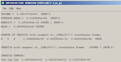
Looking at the mass properties report, there is a section labeled:
CENTER OF GRAVITY with respect to <model name> coordinate frame:


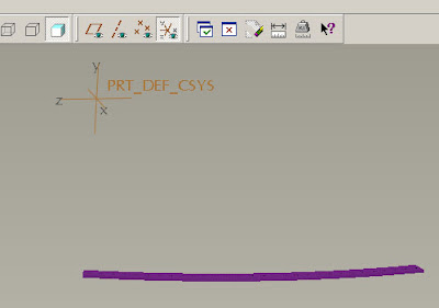
Turn on coordinate frames, and find the one that corresponds to the model's origin. The x, y, z here correspond to the x, y, z directions given in the mass properties report.


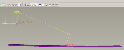
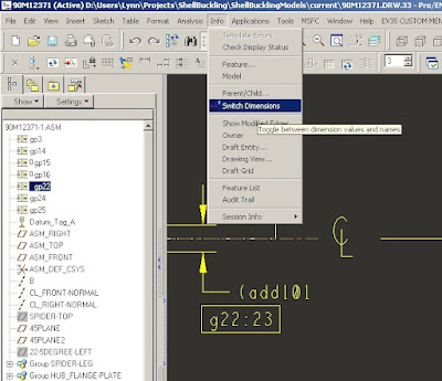
Place a point in the model, with dimensions referenced from the origin. Place planes if necessary for proper placement of the point. Don't worry yet about the actual numeric values. Below is a point, with the dimensions switched (Info/Switch Dimensions) so that the dimension labels are shown.


There are default parameters that contain the CG values generated in the mass properties report. They are:

PRO_MP_COGX
PRO_MP_COGY
PRO_MP_COGZ

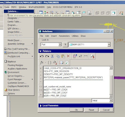
Open the Tools/Relations panel and enter in the following relations, replacing the d27, d28, and d29 with the actual dimension labels in your model. The "$" preceding each line allows the dimension to accept a negative value, as is the case for "y" in this example. Take care to verify that the assignments are correct, or the point will not end up at the right place.

$d27 = PRO_MP_COGX
$d28 = PRO_MP_COGY
$d29 = PRO_MP_COGZ


Now there is a point that is at the cg of the model, and it is available for dimensioning off of in a drawing. Placing an axis or a plane through the point will let you pull a centerline into your drawing also.

Friday, December 05, 2008

Exploded View

Open "view manager", select the "Explode" tab, and make a new exploded view. Go to the "View" dropdown in the main window, and select "Explode/Edit Position". Select components and move to the desired "explode" location.

Thursday, September 11, 2008

Ghost a Component

If you need to show a component on a drawing sheet as "ghosted", pick View/Drawing Display/Component Display, select the display style, and Ctrl-click the components that you want to use phantom lines.

Monday, July 14, 2008

Show Weight in a Drawing Note

Begin in the part or assembly file that the drawing is attached to.

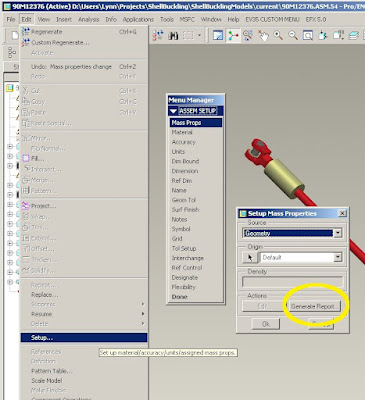
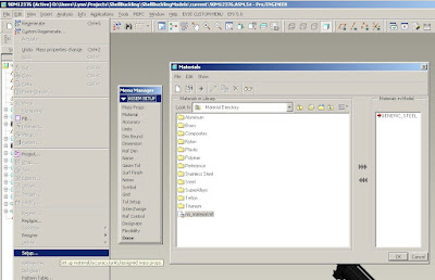
- Make sure the material is assigned in the model, or in the parts if it is an assembly. To do this, pick the drop-down Edit/Setup, and pick "Material", then choose an appropriate material. (More details on this)

- Run a Mass Props report on the model or assembly: drop-down menu Edit/Setup, and pick "Mass Props", then click "Generate Report".

WARNING!
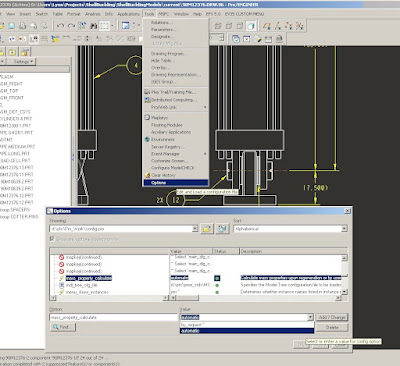
Mass_property_calculate has the default setting of "by_request"; mass properties report must be run to update the weight each time model changes are made. Set it to "automatic" by picking Tools/Options, type "mass_property_calculate", choose "automatic", "Add/Change", "Apply", then "Close".


- The parameter PRO_MP_MASS should now contain the weight of the part/assembly.

- Choose Tools/Parameters and make sure that there is one called "MASS", with type = "Real Number"


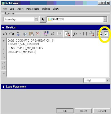
- Choose Tools/Relations, and add the following line if it is not there already:
MASS=PRO_MP_MASS

- In the Tools/Relations panel, click the "Execute/Verify Relations..." button. This activates the relation.


In the Drawing:
This text: "&MASS" in a note or table will display the mass. If more than one model is attached to the drawing, the mass will be for the active model. The id for the active model will be added in the text, which can be seen when the text is edited and when Info/Switch Dimensions is selected. For example, &MASS:5 is the mass for model id 5.

- Less decimal places:
To control the number of decimals displayed, add [.#] to the right of the callout, where # is the number of decimals to display. For example:

For zero decimals: &MASS:5[.0]
For two decimals: &MASS:5[.2]

Monday, July 07, 2008

Add Bolt Sizes to Hole Tool

If the thread size you want is not in the drop-downs for the Hole Tool, you can add one. Browse to C:\ptc\proeWildfire30\text\hole and open the appropriate thread file with WordPad. Following the format exactly, add the data for the new thread.

You will need to restart Pro|E to activate the new thread table.

Troubleshoot:
1. If the thread table you edited no longer shows up, there is something incorrect in the data that was added. Look carefully, scroll all the way to the right, and make sure all columns have data.

2. If the table shows up, but your edits do not, Pro|E may be looking at a different directory than that of the table you edited. In Pro|E, select the dropdown Tools/Options, then find the "hole_parameter_file_path" directory. The actual location of the hole tables is listed there.

Friday, June 27, 2008

Layers and Hiding Stuff

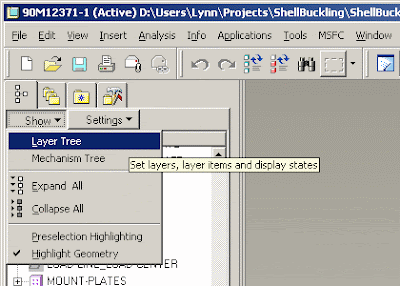
Putting things on layers makes it easier to hide and show what you want to see. Click on "Show", and pick "Layer Tree" to view the model layers. Pick "Model Tree" to go back. The layer tree is an alternate organizational view of the model elements. If it is an assembly file, you will see layer names for all of the parts in the assembly also. Layers will same-names will be grouped, and identified by the file name where they are located.


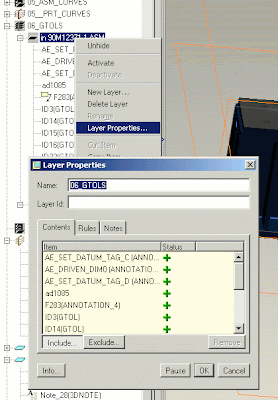
To move something to a different layer, find the layer (not the layer group, which is above- parent to- the layer), and right-click on it. Select "Layer Properties", and a window will pop up. Make sure "Include" is selected. Now pick an item in the model window, and it will be added to that layer.

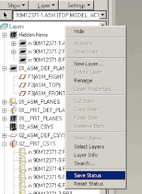
To hide an item, right-click the item , and choose "hide". To keep the item hidden after you close and re-open the file, right-click in the layer tree view, and pick "Save Status".

Viewing Geometric Tolerances (GDT) frame in the Model Tree


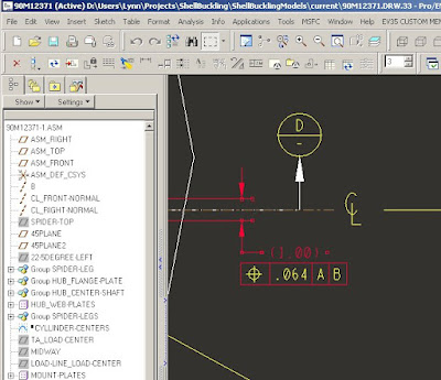
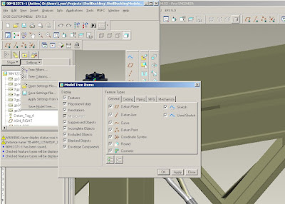
Sometimes it's hard to edit a GDT frame in a drawing, especially if the GDT is attached to a dimension. The GDT frames can be shown in the tree view of the model or the drawing file by selecting "Settings/Tree Filters" and checking the box next to "Annotations". They are then easily selected for editing.


To make sure you're editing the correct frame, from the dropdown in the drawing, pick "Info/Switch Dimensions", and see the number of the frame you want to edit; the number matches the item in the tree view.

I was not able to get the right-click menu from the tree in the drawing file, but it works fine from the tree in the assembly model file. Select "properties", and edit the frame.

Thursday, March 27, 2008

Lock Part Number to File Name

If your part number is the same as the file name, you can write a relation to link them.

From the Dropdown menu: Tools/Relations

add this line:
part_number=rel_model_name

Tuesday, March 04, 2008

Pro|E: Location Callouts: What Sheet and Grid a View can be found on.

This is used to create a parametric note that identifies the sheet and/or drawing zone a specific view (detail, section, etc) is located in on a drawing. A reverse callout is also available, giving the location of the detail or cross-section's parent view. For drawing zone callout, a grid must be defined.

Callouts:
  • Grid letter and number: &pos_loc:view:<view name>
  • Sheet number: &sheet:view:<view name>
  • Where the parent view is: &pos_loc:parent_note:<view name>
  • What sheet the parent view is on: &sheet:parent_note:<view name>
<view name> is the name in the properties pop-up for the view. If it's not found, then *** will be displayed. It fails if there is a "-" in the view name.

Grid Setup: To make the grid callout work, you will need to define a "Location Callout Grid" in the format file (.frm) for your drawing. In that file pick File>Page Setup, then on the Location Grid menu, click Define and follow the steps.

Example Drawing Note:

- See Detail A at B2 on Sheet 3.

Callout for Note:
In the note's properties window, type:

- See Detail A at &pos_loc:view:detail_a on &sheet:view:detail_a


Wednesday, February 27, 2008

Pro|E: Change BOM balloon type

If the default BOM balloon bubbles don't meet your standards, you can replace them with custom "symbols".
  1. From the Dropdown menu: Table/BOM ballooons....
  2. To change
    1. All balloons: Pick "Change Type", then click the repeat region of the table.
    2. Selected Balloons: Pick "Alt Symbol", then select those balloons you want to change. This appears to work only if "Change Type" has been done on the balloons first.
  3. Pick Custom/Retrieve, and browse to the desired symbol file.
  4. If the symbol has variable text such as \index\, the index numbers from the table will be filled in on the symbols. It looks like variable text that is _not_ found in the table is not editable. I'm looking for a work-around for that.

Pro|E: Table Line Display

Right-click the table, and pick Line Display. This lets you turn the lines on and off without affecting the cells.

Thursday, February 21, 2008

Links for Design Stuff

Paint FED-STD-595 and swatch
Units Conversion
ProE tutorials
Hoist rings they like and ADB Hoist Rings
Weld symbols

Pro|E: Relations in Tables

Things in tables are "Report Symbols"
If your BOM table is not nice and vanilla, you may need to customize the report symbols, since you cannot hand-edit in the repeat regions. To do that, make a relation (formula/program) and use it as a Report Symbol in your table.

To create a relation:
  • Pick Table/Repeat Region/Relations, then click the table.
  • Write a relation (formula); if rpt.qty is not available, do Parameters/Add Parameter.
  • To use a report symbol in a relation, replace "." with "_", example: &rpt.qty becomes rpt_qty.
To use a relation:
  • Double-click the repeat cell.
  • Pick the report symbol: rpt.../rel.../User defined
  • Enter the variable that is defined by your relation

Example: an OR statement

IF asm_mbr_part_number == "90M12373-1" | asm_mbr_part_number == "90M12375-2"
qty_fn2 = "-"
ELSE
qty_fn2 = rpt_qty ENDIF

In this example, qty_fn2 is the variable that can be used as a Report Symbol. asm_mbr_part_number is a Report Symbol in a different column of the table. Note that "." has been replaced with "_"; this replacement is required for using Report Symbols in Relations.

Pro|E: Relations programs

For some reasonable help with writing a Relation:

From the Dropdown Menu, select Help/Help Center
>Functional area: Fundamentals
>Modules and Books: -Pro/ENGINEER Fundamentals

For a list of Operators, pick Relations and Parameters/Relations/operators and Functions Used in Relations/About Operators Used in Relations

== Equal to

> Greater than

>= Greater than or equal to

!=, <>,~= Not equal to

<>

<= Less than or equal to

| Or

& And

~, ! Not

Pro|E: Make a Symbol

For labels, notes, weld symbols, flags, BOM balloons, etc, use a Symbol. When there isn't one that meets your standard, or there's something you keep remaking alot, like a material note or Centerline symbol, create your own Symbol. Place them all in a "symbol palette" for quick access; this is actually a drawing with a special name and location. Save them as separate files to allow operations like changing BOM balloon type.

Creating the Symbol

  1. Open a drawing, or a symbol palette drawing such as C:\ptc\proeWildfire30\symbols\palette\draw_symbol_palette.drw
  2. Draw/create the item you want to make into a symbol, then copy it. Surrounding text in the symbol with "\" makes it editable, for example: \text\
  3. From dropdown menu, pick: Format/Symbol Gallery pick "define"
  4. Follow the steps to define the symbol.
  5. The original sketching that the symbol was created from is not in fact a symbol, so you may want to delete it from the drawing.

Placing the Symbol:

Using the "Insert a customized instance of a drawing symbol" button:

Select the new symbol by name from the dropdown-carrot, and place the symbol in the drawing.

Saving in a Palette:

Open a symbol palette drawing, place the symbol in it, and save. The symbol is now available to place from that palette. Set default palette in Tools/Options/pro_palette_dir, then browse to the file

To save as a separate symbol file:

  1. From dropdown menu, pick: Tools/Options, then find "pro_symbol_dir". The path listed in the "Value" field is your default path. This is where your new symbol file will be written. If you want to change the path, write down the default first so you can revert back later. My default path is I:\Pro_E\Pro_Stds\et50_custom_config\et50_symbols
  2. From dropdown menu, pick: Format/Symbol Gallery
  3. Choose "write", select the desired symbol, and save it out.
  4. Set the pro_symbol_dir back to your default.

Pro|E: Create a reference datum plane:

To use GDT frames, you need defined datums. Unfortunately, the terminology is blurred here; a datum used for creation of geometry is not usable in a GDT frame until it is annotated as being a named "Datum".

To make a GDT datum plane:
Create a regular datum plane, if there isn't one already. There are at least two ways to annotate it as a GTD datum plane; here's one:

In the model file, click "Insert an annotation feature", if it's on the toolbar. It looks like a sticky note. If not, pick "Insert/Model Datum/Annotation" from the drop-down menu.

Pick "Add", then "Set Datum Tag".

Select the desired datum plane and placement features. Be careful to click "ok", "done", etc. on the pop-up dialogs, or you will need to restart the process. It does not strike me as "friendly".

Pro|E: To remove cross-section arrow text:

Select dropdown: File/Properties

Choose: Drawing Options

Set "crossec_text_place" to "no text"

Pro|E: Bill of Materials (BOM) Table

Select dropdown: Table/Insert/Table From File

Browse to, and select: bom_table.tbl, downloadable from bom_table.tbl.3

In each individual model file in the assembly, do the following:

- Select dropdown: Tools/Parameters

- Click the green "plus", and add an entry named "REMARKS". Set the type to "string" - Fill in data for the following entries:

>> PART_NUMBER (the actual drawing dash number for the part)

>> DESCRIPTION (name of the part)

>> PART_TYPE (F for "fabricated", P for "purchased", etc.)

>> REMARKS (usually this is a material note, or a vendor part number)

Return to the drawing, and Regenerate/Automatic. Incomplete entries in the table that lack a part number indicate models that have not had the Parameters filled in.

Pro|E: Set Density

Select the material
Setting the density by selecting a material will set the density and material name listed in the Tools/Parameters window. It also sets and freezes the density used in the Analysis/Model/Mass Properties window, which is used for calculating the weight of the part.

To select a material:
From the Dropdown menu: Edit/Setup
Select: Material
Browse to the desired material file.
The active material's name will have a red arrow pointing to it.


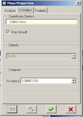
From the Dropdown menu: Analysis/Model/Mass Properties Pick the "Definition" tab
The density is shown in a ghosted field. If no material has been assigned, the value will be editable.

Monday, January 21, 2008

Fasteners

McMaster-Carr


page 3060
Hex Head Cap Screws

page 3104
Hex (Full) Nuts

page 3130
Flat Washers Data Sheet

Sunday, November 11, 2007

Acronyms

Acronyms

STA: Structural Test Article
STE: Special Test Equipment
NDE: Nondestructive Evaluation
MDA: Manufacturing Development Article
TPS: Thermal Protection System
CLV: Crew Launch Vehicle
US: Upper Stage
S&T: Structures and Thermal
LVDT: Linear Variable Differential Transformer: a displacement measuring instrument
DCTC: ? maybe a way to use LVDT?
psig: psi gauge
RCS: Roll-Control System

Item names

Common Bulkhead, ~18' dia; 3' dia access port
LH2 and LOX Tanks
y-rings
bolting ring
LOX Aft Dome, Aft Skirt, and Interstage

Wednesday, February 21, 2007

Shaders

In Creator:

Within Creator, there is a shader palette. Shaders are assigned one only, per-polygon. Each palette entry can specify a vertex shader file and entry point and a fragment shader file and entry point. They can be the same file, or not. Shader file paths may be set as absolute, relative, or "no path". Only CG and CgFX shader types are rendered in Creator. I have used ARBVP1, because it has built-in value names that can be accessed by the shader. VP20, VP30, and "use latest" are also available options.

The shader effect can be viewed in the Creator window by setting the texture layer in the "view" panel to "blend", and then starting the shader. If the shader uses fog, the fog control dialog also needs to be started.

Accessing VTree's built-in shaders from a model

http://workie.pbwiki.com/f/built_in_shaders.htm

World map links

Python


Python homepage/download
Python Learning Foundation
wxPython
Useless Python

GUI

Install for python version:

Import system objects

import glob
import os

Import MS Windows and Excel objects

from win32com.client import Dispatch ## Import win32 objects
xl = Dispatch('Excel.Application') ## define Excel file type

Using Dispatch

xl.Workbooks.Open(workbook) ## Open workbook
xlSheet = xl.Sheets(sheet) ## Open sheet
celldata = xlSheet.Cells(rowNum, colNum).Value ## Read value from a cell
xlSheet.Cells(rowNum, colNum).Value = newvalue ## Write a value to a cell
sleep(10) ## Give it a chance before closing the workbook
xl.Workbooks.Close()

XML

XML for Py tutorial

import xml.sax
import xml.parsers.expat
From ArcGIS page:
An ArcXML DTD. An XML Data Type Definition (DTD) is available for use with ArcXML 1.1. This DTD defines the structure rules for the elements and attributes in ArcXML and checks for document validity. The DTD can be used with many XML editors, but since ArcIMS requires UTF-8 encoding, editors that support UTF-8 encoding are recommended. The following two editors support UTF-8 encoding:

XML Spy: http://www.xmlspy.com
Xeena: http://alphaworks.ibm.com/tech/xeena

Basic guide to arcXML

Wrappers for other languages/API's

Try SWIG or Sip to make wrappers for C

Monday, January 31, 2005

Monitor Calibration

Do these two images look alike when you squint a little bit?


If they don't, your monitor is calibrated differently than mine, and my images will look different to you. Most likely, my images will be pale or "washed out" to you. Check out my monitor calibration article, complete with explanations, procedures and calibration images. This was written for CRT monitors, but still has value for LCD's.