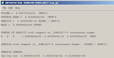
First, assign materials to the part, or parts if it's an assembly, then run a mass properties report. This is done through the Edit/Setup menu. For more details on this, read how to put weight into a drawing note.
Looking at the mass properties report, there is a section labeled:
CENTER OF GRAVITY with respect to <model name> coordinate frame:

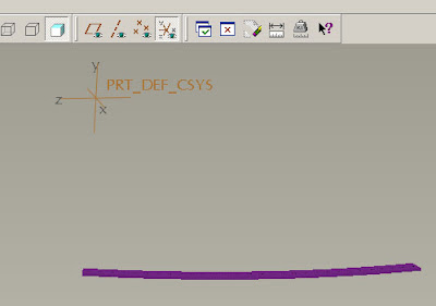
Turn on coordinate frames, and find the one that corresponds to the model's origin. The x, y, z here correspond to the x, y, z directions given in the mass properties report.

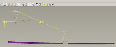
Place a point in the model, with dimensions referenced from the origin. Place planes if necessary for proper placement of the point. Don't worry yet about the actual numeric values. Below is a point, with the dimensions switched (Info/Switch Dimensions) so that the dimension labels are shown.

There are default parameters that contain the CG values generated in the mass properties report. They are:
PRO_MP_COGX
PRO_MP_COGY
PRO_MP_COGZ
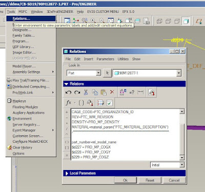
Open the Tools/Relations panel and enter in the following relations, replacing the d27, d28, and d29 with the actual dimension labels in your model. The "$" preceding each line allows the dimension to accept a negative value, as is the case for "y" in this example. Take care to verify that the assignments are correct, or the point will not end up at the right place.
$d27 = PRO_MP_COGX
$d28 = PRO_MP_COGY
$d29 = PRO_MP_COGZ

Now there is a point that is at the cg of the model, and it is available for dimensioning off of in a drawing. Placing an axis or a plane through the point will let you pull a centerline into your drawing also.
No comments:
Post a Comment